TRS-80 Model 100 information
This document contains information about the TRS-80 Model 100
Power
The device is either powered by AA batteries, or a 6V DC power supply. An internal 3.6 V battery keeps the memory functioning if no other power source is available.
Batteries
4 AA batteries can be used to power the device for approximately 20 hours. You do not need to remove them when plugging in a DC connector. The connector physically disconnects them when used.
NiMH batteries have only limited use since they provide less voltage.
Alkaline batteries: 4 × 1.5 = 6.0 Volt
NiMH batteries: 4 × 1.2 = 4.8 Volt
Some device functions may not operate properly on NiMH.
Barrel connector
6V DC Allows powering the device indefinitely.
People back then were savages that wired the barrel connector backwards. Modern devices use the pin as positive and the sleeve as ground. For the model 100, it's reversed.
When you buy a power supply, you either need to make sure it is wired the same way, rewire it, or buy a universal power supply that allows you to plug in the connector backwards.
Memory backup
This 3.6 volt rechargeable battery is used to power the RAM whenever no other power source is available. It's very slowly charged by either the Barrel connector or the AA batteries. it doesn't holds a lot of charge (approx. 50 mA). it will power the RAM for hours or even days while you swap your batteries.
You want to replace this now. Due to the age, it's likely already leaking. The component is soldered but easily accessible. Instructions for this at the bottom.
Resetting
You may need to reset the device because it's no longer working. There's multiple ways of doing this with various effects.
If your device simply doesn't turns on, make sure the batteries are installed correctly, have a charge, and that the memory power switch is set to "ON".
Regardles of what you try, the ROM which holds the built-in programs (BASIC, TELCOM, TEXT, SCHEDL, ADDRESS) will retain these programs.
Power cycle
Simply turning the device off and on again may re-enable the ability to exit out of a stuck condition using SHIFT+PAUSE.
This will retain RAM contents.
Soft reset
If power cycling does not work, a soft reset mey help. Press the reset switch on the back briefly to force the device back to the menu. You need to do this while the device is running.
This will retain RAM contents.
Hard reset
A hard reset will erase all memory contents. You want to do this if the soft reset is not resolving your issue.
- Turn the device off
- While holding CTRL+PAUSE, turn the device back on
This will clear RAM contents.
Full wipe
If even a hard reset is not helping, you can perform a full data wipe by de-energizing the RAM. This will effectively return the device into the state it had fresh out of the box. Unless you really screwed up (well done by the way), doing a hard reset instead is usually sufficient.
- Remove all external power sources (AA batteries and DC connector)
- Cut the internal power source by setting the memory power switch to "OFF"
- Wait for 5 minutes
- Reinstall the AA batteries or connect external DC power source
- Set the memory power switch back to "ON"
This will clear RAM contents.
Data transfer
Data transfer to/from the model 100 is an essential task if you want to keep the device even moderately useful.
The most common way of transferring files to/from the device is via serial port.
Possible means of interfacing are:
- Virtual disk drive (see: NADSBox) via serial port
- Via Serial
- Via Modem
- Via Barcode (input only)
- Via Printer (output only)
- Via Tape
Disk drive
- Speed: Identical to serial port
- Reliability: High
Disk drives (either an original or an emulated one) are ideal for file transfer and storage. The actual speed depends on the storage media and driver implementation.
I/O Ports
This chapter is a list of the available ports and their speed/reliability for data transfer.
Serial
- Speed: 75 - 19200 baud
- Reliability: High
The serial port certainly is your port of choice for file transfer. USB to serial adapters are available for cheap, or you can buy yourself a serial PCIe card.
PCIe vs USB
The PCIe card is the preferred way as it provides maximum compatibility with serial port standards. They also often come with two ports, giving you two serial lines cheaper than two USB devices would. They also usually occupy the legacy serial I/O addresses and IRQ, which means they will work natively with every OS made since the IBM PC standard was established.
They are obviously not an option for laptops and other small computer that lack PCIe ports or the space to fit a serial port on the outside.
USB adapters usually work fine but may show weird behavior as they sometimes come with big buffers or fail to maintain proper operating voltage.
The RS-232 standard is fairly generous in regards to voltage levels:
- Valid signal is in the range of 3V to 15V (positive or negative to the ground pin)
- Voltages of the two devices doesn't need to match
- Devices must withstand indefinite short circuits
- Devices must tolerate an open circuit voltage of ±25V
Because of these characteristics, some USB to serial adapters use the USB 5V voltage for signaling. While this is permitted as per the standard, it's at the lower end of the spectrum. Some devices may fail to properly communicate at those levels. In that case you either want to switch to a PCIe adapter, or try to find a better (usually more expensive) USB adapter.
Cables
The model 100 has a 25 pin port while RS-232 usually uses a 9 pin port.
In regards to electrical wiring, these ports are identical with the only difference that the 9 pin port lacks a protective ground pin, which is not needed anyways as the cable itself is shielded, and the shield can be used as protective ground.
Pin layout
| Signal | DB-9 | DB-25 | Sender |
|---|---|---|---|
| TxD | 3 | 2 | DTE |
| RxD | 2 | 3 | DCE |
| DTR | 4 | 20 | DTE |
| DCD | 1 | 8 | DCE |
| DSR | 6 | 6 | DCE |
| RI | 9 | 22 | DCE |
| RTS | 7 | 4 | DTE |
| CTS | 8 | 5 | DCE |
| G | 5 | 7 | Common |
| PG | N/A | 1 | Common |
Description of signals:
TxD: Transmit. Data sent from DTE to DCE
RxD: Receive. Data send from DCE to DTE
DTR: DTE is ready to receive, initiate, or continue a call. This is the DTE version of the DSR pin.
DSR: DCE is ready to receive and send data. This is the DCE version of the DTR pin.
DCD: DCE is receiving a carrier from a remote DCE. A modem will assert this pin as soon as the handshaking with the remote modem is complete. It's basically the "connection established" pin. If the DCE is not a modem (or merely simulates one) it usually asserts the pin whenever a piece of software has the port open.
RI: DCE has detected an incoming ring signal on the telephone line. Traditionally, the modem would assert this pin when a ring signal from the telephone line was detected. The pin would be high in sync with the 100 volt ring signal from the line, allowing the DTE to detect the type of ringing signal.
In a DTE, the RI pin is often connected to a hardware interrupt. The model 100 has this line disconnected though.
RTS: DTE requests the DCE prepare to transmit data. This is used with the CTS signal, but they're not opposites. This signal was used in the past for half duplex connections (TxD and RxD over a single shared wire). If RTS is asserted, the DTE wants to send data to the DCE.
This signal lost all original meaning and is now used for flow control. The RTS signal is asserted by the DTE whenever it's ready to receive data.
CTS: DCE grants the DTE permission to send data. This is used with the RTS signal, but they're not opposites. When the DCE is ready to receive data from a DTE that asserts the RTS line, it asserts the CTS signal.
This signal lost all original meaning and is now used for flow control. The CTS signal is asserted by the DCE whenever it's ready to receive data.
G: Common ground. This is the pin that is used for the other signals as return path and acts as the 0V reference for other signals. Not to be confused with PG. Should not be connected to PG.
PG: Protective ground. This is the pin (or cable sheild) for protective grounding. Not to be confused with G. Should not be connected to G.
The protective ground is used to shield the cable from external interferences. It also connects the two chassis of the devices together.
DTE vs DCE
Traditionally, DTE is the terminal (Data Terminal Equipment), DCE is the device you communicate with (Data Communication Equipment). Simply put, the DTE controls the DCE. This means the DTE is usually the bigger, more complicated device.
Before you had individual computers you had terminals such as the VT100 that communicated via serial link with a remote computer and merely served as display and input device. These were known as terminal (hence DTE). The terminal communicated with a modem (the DCE) that sent the data off to the other end. The schema looks like this:
DTE → DCE → Network → DCE → DTE
Whether a device is DTE or DCE can usually be seen at the serial port. A DTE has a male DB-9 port or a female DB-25 port. Vice versa for DCE.
Nullmodem
When intended to connect two DTE devices together directly, a so called nullmodem cable or adapter can be used.
A nullmodem cable handles the 9 serial signals as follows (A and B used as the two cable ends):
- TxD-A connected to RxD-B
- RxD-A connected to TxD-B
- DSR-A connected to DTR-B
- DTR-A connected to DSR-B
- DCD-A connected to DSR-A (and thus DTR-B)
- DCD-B connected to DSR-B (and thus DTR-A)
- RTS-A connected to CTS-B
- RTS-B connected to CTS-A
- RI-A disconnected
- RI-B disconnected
- G-A connected to G-B
- PG-A connected to PG-B
Flow control
3 types of flow control exist and can be mixed.
- DTR/DSR: Uses DTR and DSR pins to signal if ready to receive
- RTS/CTS: Uses RTS and CTS pins to signal if ready to receive
- XON/XOFF: Uses ASCII CTRL+Q and CTRL+S to signal if ready to receive.
Common mode
The most common mode for modern serial devices is 88N1D,
which is 9600 baud, 8 data bits, no parity, 1 stop bit, no software flow control.
115200 baud is not availavble on the model 100 due to hardware limitations.
Detecting a connection on the RS232 port
If you want to write software that communicates with your Model 100, you can check the "carrier detect (CD)" pin. The model 100 asserts this pin whenever the serial port is opened by BASIC, TELCOM, or a custom program.
Note: Signal pins may assert themselves under some conditions. If you use the CD signal, wait for 200 ms, and check it a second time.
The CD (and other) pin briefly may get asserted when the device is turned on, or when the serial cable is plugged in/out while the device is already on.
Speed limits
These are the speed limits imposed due to the system speed and architecture (as vieved from the model 100)
| Application | Send | Recv |
|---|---|---|
| BASIC | 19200 | 600 |
| TELCOM | 19200 | 300 |
Going above the receiving speed will work for short bursts of data.
The speed limit is mostly given by software. BASIC needs time to tokenize the lines transmitted. TELCOM dumps all text to the display, which is slow.
An optimized assembly program could likely exceed these speeds.
Modem
- Speed: 300 baud
- Reliability: Medium
The modem can be driven in either modem mode (DIR), or accoustic coupler (ACP) mode. With modem mode, it directly plugs into your phone jack, with ACP mode it must connect to a phone handset.
Be aware that many modems no longer support 300 baud mode and may not communicate properly with your model 100.
Tone dialing
The modem only supports pulse dialing, which has been completely phased out on public telephone networks. Some switching equipment may still support it for backwards compatibility, but with VoIP, it's essentially dead now.
A translator is needed to make it function on modern phone lines (see: Dialgizmo)
If you don't want to do this:
- Dial the desired number from a phone connected to the same line
- Once ringing starts, put the modem on line
- Hang up the phone
Alternatively, if possible you can call the modem from the other one, because answering calls still works as intended. Make sure the switches on the left side of the device are in "DIR" and "ANS" mode.
Final alternative is the accoustic coupler mode, for which you attach the two adapters to your phone handset and then simply dial the number from there. The switches should be in "ACP" and "ORIG" mode for this.
Pinout
The pinout of the port is as follows:
| N° | Symbol | Description |
|---|---|---|
| 1 | TL | Telephone |
| 2 | GND | Ground |
| 3 | RING | Tel line |
| 4 | MIC | Microphone |
| 5 | SPKR | Speaker |
| 6 | VDD | N/A |
| 7 | TIP | Tel line |
| 8 | RP | Ring paluse |
The order of the pins in the port is as follows:
7-1-4-2-5-3-8
This is the order when you look at it and go in clockwise direction from the top notch. This means 7 is in the top right corner and 8 in the top left. Pin 6 is the center pin.
Pin 1 is used to forward the telephone signal to your existing telephone. It connects internally to pin 7 when the modem is not in use.
Pin 3 is probably shared between your desk phone and the model 100 and simply looped through.
Pin 6 lacks a documentation about exactly how much voltage is applied.
Pin 8 is named "ring paluse" in the manual, which is probably a misspelling of "pulse". The pin might be for some phone systems that send the ringing pulse on a different wire.
VoIP
Modern VoIP lines can often cause problems with modems. The model 100 should not be affected by this because it only uses 300 baud, but if you encounter problems, check if any compression is active on the line and disable it.
Barcode
- Speed: Unknown
- Reliability: High
The BCR port is a unidirectional serial port that runs at 5 volts and lacks a proper protocol. The reader can assert a certain pin high or low, and you can read the pin at I/O port 175 (bit 3). Since the port outputs 5 volts, you can use it to power low current USB devices.
Printer
- Speed: Unknown
- Reliability: Paper
Printing your stuff is a way of getting it out of the model 100. I guess if you know your way around electronics you could use an arduino to act as a virtual printer and have it send the characters over USB to your computer.
Due to the nature of printers, this port is for output only and cannot receive files.
Tape
- Speed: 1500 baud
- Reliability: Medium
You can connect the audio inputs and outputs to your computer and record and play back audio this way. Getting the volume right can be a bit tricky.
Note: The cable that comes with the model 100 shorts the right channel to ground. This means you want to record and play back from the left channel only.
The motor port
The TRS can turn the tape motor on and off on command. This is done via the motor cable. The plug looks identical to the record and playback plug but is smaller (2.5 mm vs 3.5 mm). The motor is on when the two metal contacts are shorted together.
You don't need this, but if you feel fancy you could build something that automatically starts and stops recording on your computer with this cable.
CPU Ports
This chapter explains CPU ports.
Note: Bits declared as "unused" should not be changed. Some registers serve multiple purposes.
General port ranges
(Port numbers given in hex)
| Port | Description |
|---|---|
| 80-8F | Device-select signal for optional IO controller unit |
| 90-9F | Device-select signal for optional answering telephone unit |
| A0-AF | Bit 0 - ON/OFF of relay for signal selection of telephone unit, Bit 1 - Generates ENABLE signal of LSI for MODEM |
| B0-BF | PIO 81c55 |
| C0-CF | DATA input/output of UART |
| D0-DF | UART settings |
| E0-EF | Keyboard return |
| F0-FD | LCD |
| FE | LCD |
| FF | LCD |
Port B
Port B (addressable as port 0xBA) controls various functions.
Layout: MSB ABCDEFGH LSB
- A: Select display chip 8
- B: Select display chip 9
- C: Enable/Disable buzzer
- D: 0=RS232, 1=Modem
- E: Power off control: Set to 1 to turn the device off
- F: Buzzer signal (cycle on/off at desired frequency to generate a sound)
- G: Serial line DTR signal
- H: Serial line RTS signal
Serial Port
You can directly control the serial port via ports BA and D8
Port 0xD8
Sets serial port parameters
Layout: MSB xxxDDCBA LSB
- A: Stop bit (0=1, 1=2)
- B: Paritiy (0=Odd, 1=Even)
- C: Parity (0=Enable parity bit, 1=Disable parity bit)
- D: Data bits (00=5, 01=6, 10=7, 11=8)
Port 0xBC and 0xBD
These ports control the baud rate.
| Baud Rate | PIO Divisor | Port BD | Port BC |
|---|---|---|---|
| 75 | 2048 | 72 | 0 |
| 110 | 1396 | 69 | 116 |
| 300 | 512 | 66 | 0 |
| 600 | 256 | 65 | 0 |
| 1200 | 128 | 64 | 128 |
| 2400 | 64 | 64 | 64 |
| 4800 | 32 | 64 | 32 |
| 9600 | 16 | 64 | 16 |
| 19200 | 8 | 64 | 8 |
| 38400 | 4 | 64 | 4 |
| 76800 | 4 | 64 | 2 |
38400 and 76800 are not selectable via regular means.
Note: For 76800 baud, the BC value can also be 1.
Port 0xB8
Writing 0xC3 to this port enables the baud rate values from BD and BC (see above).
Port 0xC8
Writing to this port sends the value to the serial port. Reading from the port gets a received value from the serial port.
Port 0xBA
This port has a few bits concerning RS232. See "Port B"
Port 0xBB
Bit 4 gets the CTS signal, bit 5 the DSR signal.
Display
The display consists of 10 display chips.
Arranged in this pattern:
0 1 2 3 4
5 6 7 8 9
Each chip handles a 50x32 section of dots. Note: On The 10 rows at the bottom of the bottom chips are not visible, effectively giving them a 40x32 area. You can still write to the invisible section.
Note: The chips are "HD44102". Documentation is still available if you want to check for additional control possibilities.
Port 0xB9
Select display chip 0-7
Layout: MSB 01234567 LSB
Port 0xBA
Select display chip 8-9 (uses high bits only).
Layout: MSB 89xxxxxx LSB
This port has multiple purposes. See "Port B"
Port 0xFE
Control register for selected display chip
Layout: MSB CCCCCCBB LSB
- C is the column you want to write to
- B is the bank you want to write to
If yo uset them separately, B is written to first.
Port 0xFF
Data register for selected display chip
Layout: MSB 01234567 LSB
MSB is the top, LSB is the bottom.
Hardware
Other hardware information
Memory battery
If you have a Model 100, the built-in battery for the memory is probably dead by now, and it may be in fact leaking already.
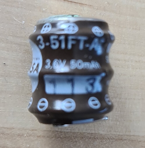
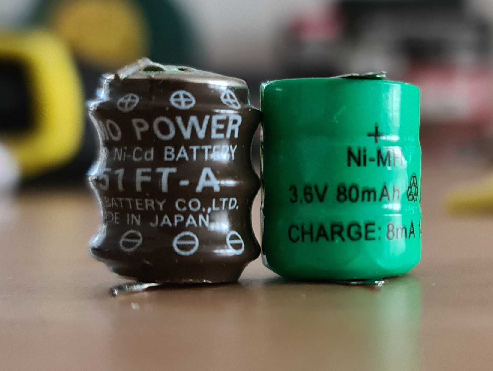
The original is a "Yuasa 3-51FT", and you can get cheap replacements from aliexpress for it. Simply desolder the old battery, and solder the new one in.
Note: The old one is a NiCd type, the new one is NiMH type. They perform mostly identical and have the exact same voltage rating of 3.6 Volts. NiCd has become more difficult to obtain in recent years.
Under no circumstances should you use Li-Ion or LiPo batteries. They will likely blow up
Tip: The Model 100 works perfectly fine without this battery, but it will reset to factory default each time you replace the AA batteries. This means it's safe to desolder it now and replace it later.
Removing/Replacing the battery
The battery is referred to as "accu" to not confuse it with the AA batteries
This is not too difficult because all components are easily accessible with standard tools. Preferrably you replace the accu, but in a pinch, you can just remove it. The device will work fine without it, but will obviously not retain any memory when you swap the AA. To safely swap the AA batteries without the internal backup battery you would need to connect a power source to the DC jack first to temporarily bridge the power gap from removing the batteries.
Do not turn the "Memory Power" switch off, even when you don't plan on installing a new accu.
Parts and tools
- Soldering iron
- Phillips head screwdriver
- Replacement battery (if you don't just want to remove the old one)
- Prying tool (a slotted screwdriver of small or medium size will do)
Before you start
Make sure you:
- Backed up everything you want to retain
- Charged your new accu (optional)
Charging is optional. If you don't do this, the accu will charge from the AA or an external power source over time. This will drain the AA faster for a while.
Removing the circuit board from the enclosure
First, make sure the device is powered off, all plugs are removed, and the batteries are out.
There are 4 screws in the bottom shell, one in each corner. Remove them all. Put the screws aside into a container to not lose them.
Carefully pull the device halves apart. They may stick together a bit due to age but are not glued by the factory. There are connecting cables on the side where the power switch is. When opening the case, it's best to pretend that this side has a hinge. This way you open it without accidentally tearing out cable connectors.
There are 4 cables that connect the main circuit board (bottom half of case) with the keyboard and display board (top half of case). Disconnect them all, then put the top half aside, it's not needed.
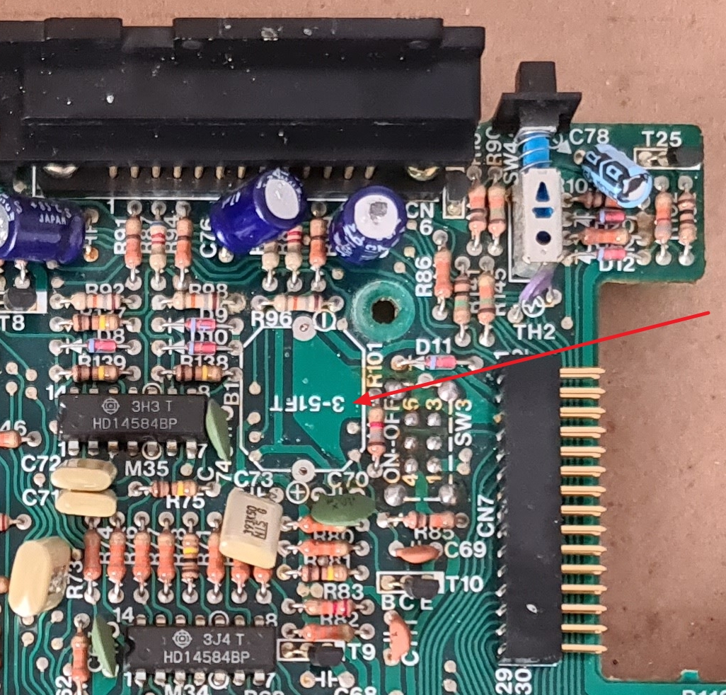
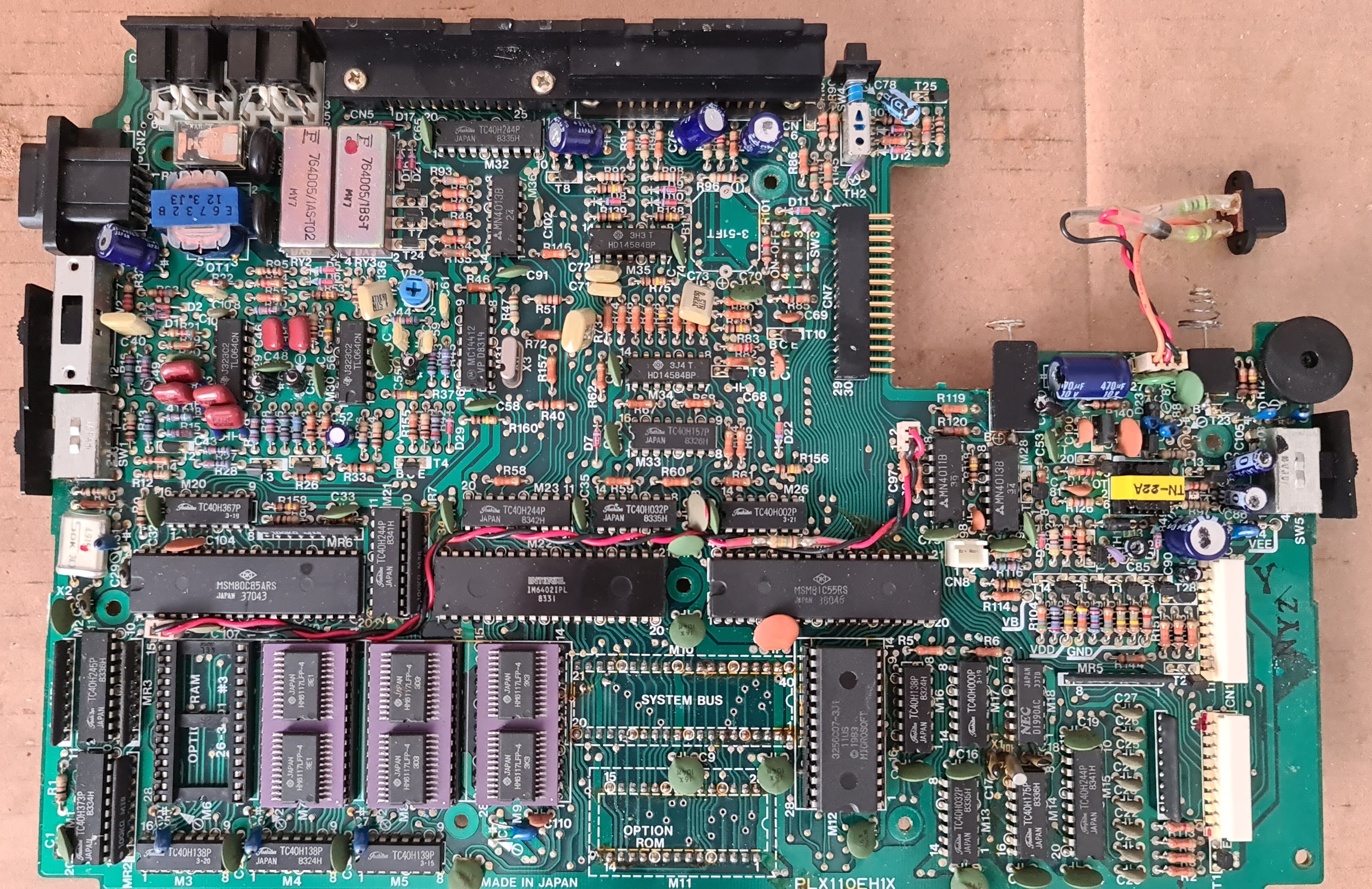
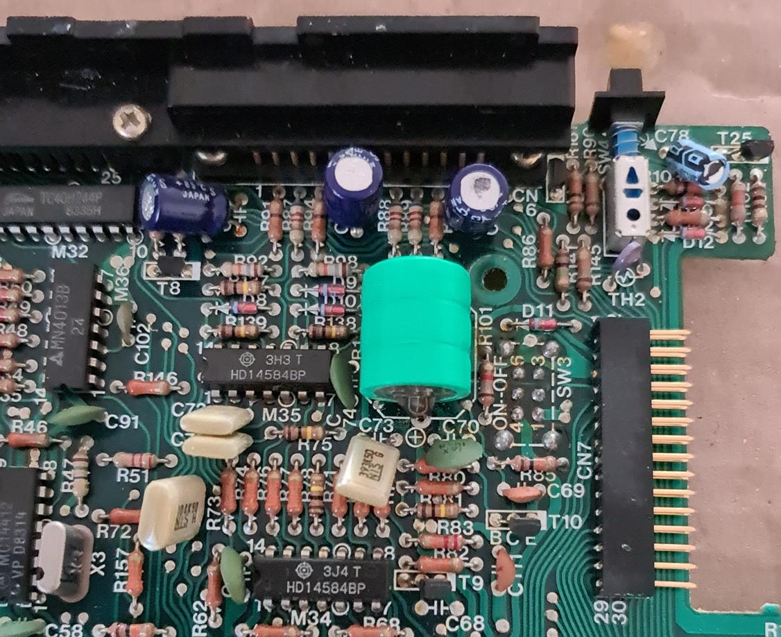
Locate the old accu.
It's located to the left side of the AA battery compartment,
mounted flat on the board, and usually brown.
It's soldered in with two terminals, one labeled with a plus sign on the board,
one with a minus sign. The accu should also contain + and - markings
as well as the text "3.6 V" and/or "Yuasa 3-51FT"
Now it's time to power up your soldering iron if you did not already
Remove all screws that hold the PCB in. They're of the same size as the case screws except for the center screw that has a plastic pin stuck to it. Do not lose the center plastic bit, or the keyboard will later feel "spongy". The plastic bit has a rubber cap on it. Do not lose that either.
Disconnect the green wire that's located next to the battery compartment, and make sure the DC jack is not stuck to the case.
Now lift the circuit board out of the enclosure. You may need to use the prying tool to get the battery contacts unstuck.
Caution! The battery terminals are soldered to the PCB. Do not break them off.
Removing the accu
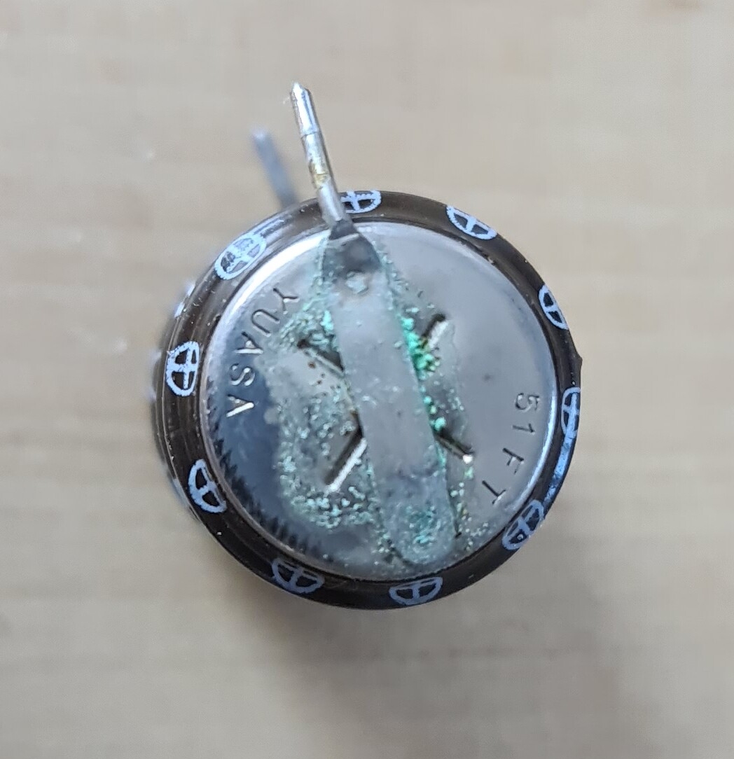
Now locate the two accu contacts on the bottom of the PCB. You can usually identify them because they contain more solder than the parts around them, and there's a "suspicious" absence of solder points between them for this otherwise fairly densly populated board.
Pull on the accu at one end with light force while holding the soldering iron to one of the contacts until it comes lose and you can pull it fully through the board. Repeat the same with the other contact to fully remove the accu.
Optional: Admire the corrosion
Installing new accu
Before you do this, check the voltage of the new accu and consider charging it if it's below 3.6V and you have the equipment for it.
Try to feed one of the pins of the new accu into the hole again. Reheat the solder until the pin pokes through. Then repeat with the other pin. Be prepared to maybe add a bit of solder if too much came off with the old accu.
Make sure you solder the new accu in with the correct orientation
The new accu is likely a bit shorter than the old one, so you may need to bend the pins slightly.
Reinstall the mainboard
You're done with the replacement. Reinstall the circuit board, reconnect the green ground cable, then the 4 cables that go to the display/keyboard. Reinsert all screws into the circuit board. Remember the one screw that differs and has a plastic clip goes into the center hole.
Finally, reassemble the case and put in the 4 case screws. Write the current date with "Accu replaced" on a piece of paper and stick it to the bottom, or use a label printer if you have disposable income.
After 10 years, replace the accu again. The sticker is there to remind you.
If you don't like this you can also put it losely inside of the battery compartment, so you get reminded of it when you replace the AA batteries.
Make sure the "Memory Power" switch on the bottom is in the "ON" position.
Charging the new accu
The accu should already arrive fully charged. If yours did not, or you forget to measure, no problem. The accu charges from either the AA batteries, or the DC jack.
Simply let the device sit 12-24 hours with batteries installed or a DC adapter connected and it will slowly charge the accu.
You do not need to turn the device on for this to work.
Testing the new accu
- Put in 4 fresh AA batteries
- Turn on the device, create a file with a few lines, and power off the device
- Remove the AA batteries, and wait 10 minutes
- Reinstall the batteries and check if the file is still there and has the correct contents
If the file is still there with correct contents, you're good to go. If the file is missing or corrupt, check the solder joints of the accu and resolder them.
Note: When you try to turn the device on in step 2 but it doesn't functions correctly, you may need to perform a hard reset.
Expansion slot
The slot can be accessed by the other door you have on the underside of your device.
It contains a socket for an extra ROM chip as well as a special socket that exposes various internal signal lines.
ROM expansion
This bus hidden behind a cover on the underside of the device allows you to plug in custom ROM chips.
There's no documentation of this in the manual, but various modern expansions exist, such as the REX
External bus
This bus hidden behind a cover on the underside of the device permits expansions.
| Pin | Signal |
|---|---|
| 1 | VDD |
| 2 | GND |
| 3 | AD0 |
| 4 | AD2 |
| 5 | AD4 |
| 6 | AD6 |
| 7 | A8 |
| 8 | A10 |
| 9 | A12 |
| 10 | A14 |
| 11 | GND |
| 12 | /RD |
| 13 | IO/M |
| 14 | ALE |
| 15 | CLK |
| 16 | /A |
| 17 | INTA |
| 18 | GND |
| 19 | RAM RST |
| 20 | NC |
| 21 | NC |
| 22 | NC |
| 23 | GND |
| 24 | INTA |
| 25 | /RST |
| 26 | /YO |
| 27 | S1 |
| 28 | S0 |
| 29 | /WR |
| 30 | GND |
| 31 | A15 |
| 32 | A13 |
| 33 | A11 |
| 34 | A9 |
| 35 | AD7 |
| 36 | AD5 |
| 37 | AD3 |
| 38 | AD1 |
| 39 | GND |
| 40 | VDD |
A term leading with "/" and in italics means it's an inverted signal
Provided the battery compartment is at the bottom right, pin 1 is at the top right, then runs to pin 20 on the top left. 21 is at the bottom right and runs to 40 on the bottom left.
There should also be markings on the PCB next to the slot.
These signals are mostly unprotected. Be very careful when hooking up hardware
A speciality about this bus is that the address and data lines are combined.
AD0-AD7 are address and data, A8-A15 is only address,
hence why some ports have "AD" and some only "A".
I believe the /A line determines the mode of the AD pins.
There is no documentation as to what all the other signals mean.
Copyright © 2022 by Kevin Gut 📧 | More services | Generated for 216.73.217.113